Reading accelerometer and gyroscope
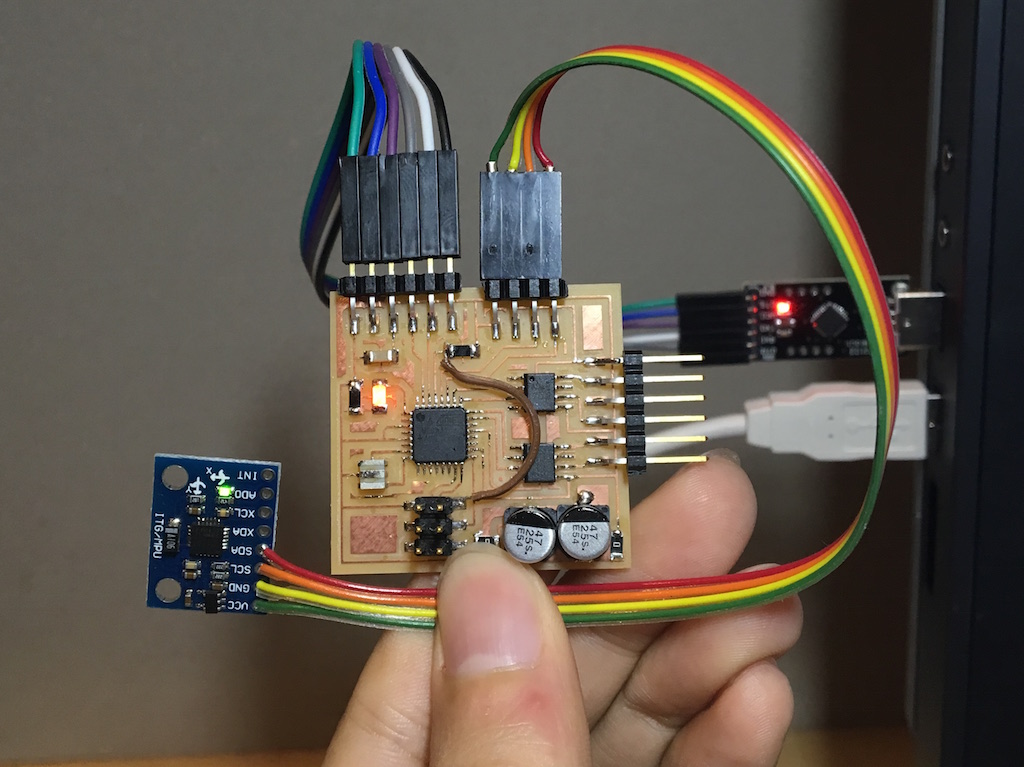
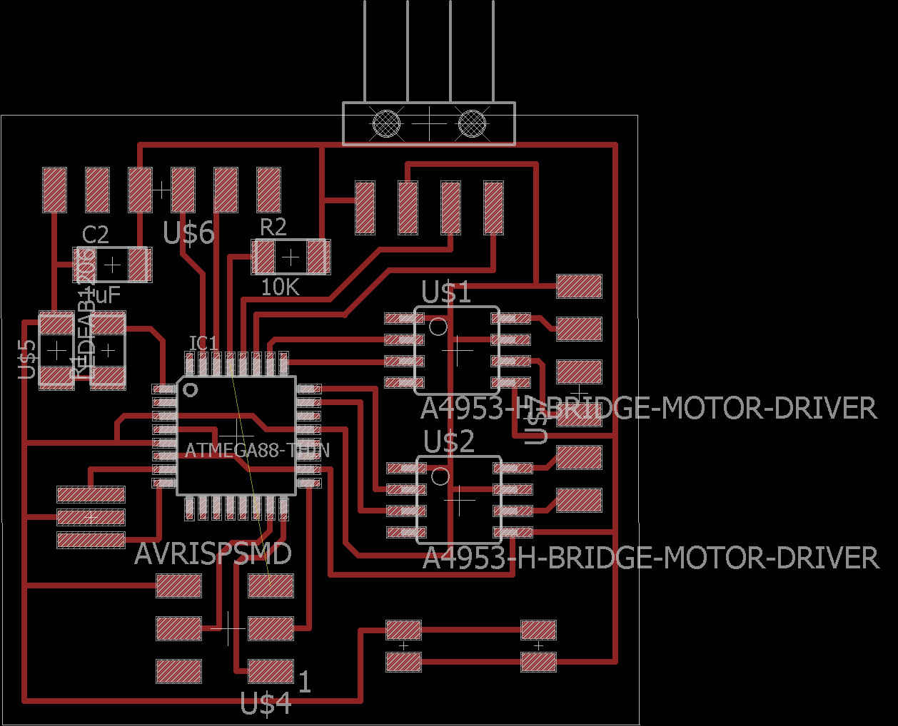
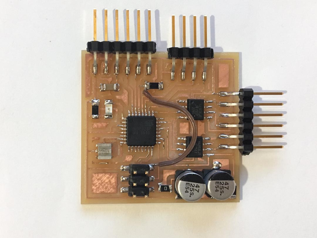
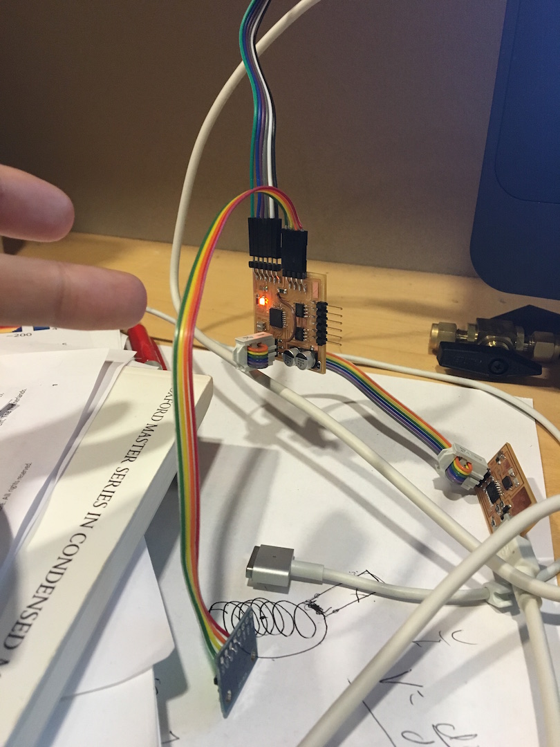
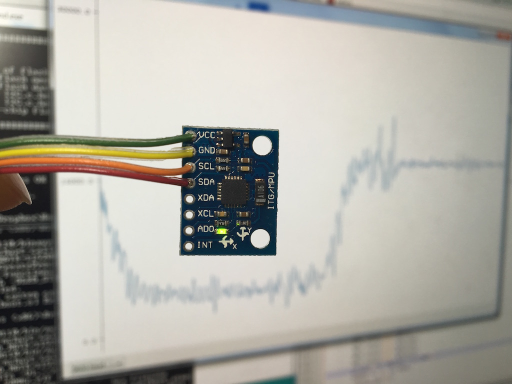
This week I designed the circuit based on Atmega328P microcontroller to read IMU (inertial measurement unit). And I also designed the board to be able to drive brushless motors for next project. The microcontroller talks with the IMU unit through I2C interface. The 6 axis IMU breakout board was bought on amazon about $3 which can read both the acceleration and rotation speed. The goal is to have the microcontroller read the IMU with I2C and pass the number to the computer through serial.
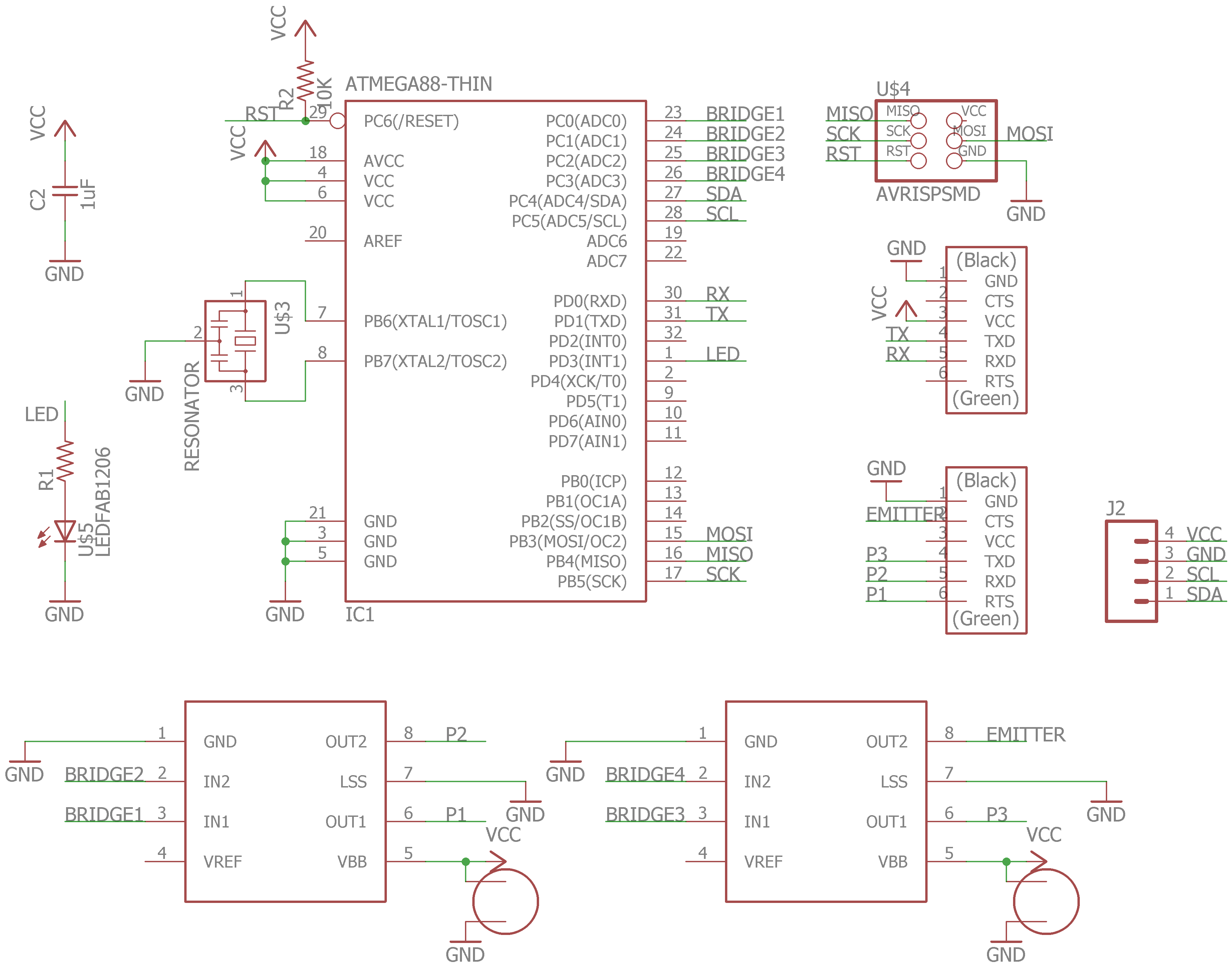
The large capacitor is for filter high voltage fluctuations when it's used to control motors. And LED is added for easy debugging. There are two H bridges which I will use to drive motor and wireless power transfer.
On the IMU, the SCL and SDA are the clock and data line. The microcontroller serves as the master and IMU is the slave.
Atmega328P already have I2C function build in the hardwire, which it calls it TWI (two wire interface). The following is the make file for it. Note the frequency is 20Mhz and the fuse is 0xD6 which sets external clock up to 20Mhz
	PROJECT=I2C
	SOURCES=$(PROJECT).c
	MMCU=atmega328p
	F_CPU = 20000000

	CFLAGS=-mmcu=$(MMCU) -Wall -Os -DF_CPU=$(F_CPU)

	$(PROJECT).hex: $(PROJECT).out
		avr-objcopy -O ihex $(PROJECT).out $(PROJECT).c.hex;\
		avr-size --mcu=$(MMCU) --format=avr $(PROJECT).out

	$(PROJECT).out: $(SOURCES)
		avr-gcc $(CFLAGS) -I./ -o $(PROJECT).out $(SOURCES)

	program-usbtiny: $(PROJECT).hex
		avrdude -p atmega328p -P usb -c usbtiny -U flash:w:$(PROJECT).c.hex

	program-usbtiny-fuses: $(PROJECT).hex
		avrdude -p atmega328p -P usb -c usbtiny -U lfuse:w:0xD6:m
Below is the C code I wrote. The first part (separated by slashes) is for serial communication with the computer; the second part is to set up functions for I2C communication and the third part is to initialize, set options and read numbers from IMU. I used pointers to pass the number out from the read function. And as each reading is 16digit long, I used uint16 and read twice, first the high 8 digits and then the lower ones.
	#define F_CPU 20000000
	#define BAUD 9600
	#define BRC ((F_CPU/16/BAUD)-1)
	#define MPU6050 0x68

	#include <avr/io.h>
	#include <stdio.h> // for serial
	#include <util/delay.h>
	#include <util/setbaud.h>
	#include <util/twi.h>
	#include <inttypes.h> // for printf uint16_t

	void uart_init(void){
		UBRR0L = BRC;
		UBRR0H = (BRC >> 8); //Baud rate setting
		UCSR0B |= (1 << RXEN0) | (1 << TXEN0); //RxTx enable
		UCSR0C = (1 << UCSZ01) | (1 << UCSZ00); //8bit char
	}

	void uart_setchar(char c) {
	    loop_until_bit_is_set(UCSR0A, UDRE0); /* Wait until data register empty. */
	    UDR0 = c;
	}

	char uart_getchar(void) {
	    loop_until_bit_is_set(UCSR0A, RXC0); /* Wait until data exists. */
	    return UDR0;
	}

	int usart_putchar_printf(char var, FILE *stream) {
	    //if (var == '\n') usart_putchar('\r');
	    uart_setchar(var);
	    return 0;
	}

	static FILE mystdout = FDEV_SETUP_STREAM(usart_putchar_printf, NULL, _FDEV_SETUP_WRITE);
	//define stream

	///////////////////////////////////////////////////////////////////////////////////////////

	void I2C_init(void){
		//TWSR = 0x00;
		TWBR = 0x5C;// TWI clock 100kHz, SCL frequency = F_CPU/(16 + 2(TWBR)*(TWSR prescale))
		TWCR = (1 << TWEN);
		//address 1101000
	}

	void I2C_start(void){
		TWCR = (1 << TWEN) | (1 << TWINT) |(1 << TWSTA);
		//twi enable/clear int flag/start (master)
		while ((TWCR & (1 << TWINT)) == 0);//? wait for TWINT to be 1?
		//if ((TWSR & 0xF8) != TW_START) return -1;
		//comfire start condition has been transmitted
	}

	void I2C_stop(void){
		TWCR = (1 << TWEN) | (1 << TWINT) |(1 << TWSTO);
	}

	void I2C_write(uint8_t data){
		TWDR = data;
		TWCR = (1 << TWINT) | (1 << TWEN);
		while ((TWCR & (1 << TWINT)) == 0);//? wait for TWINT to be 1
		//if ((TWSR & 0xF8) != TW_MT_SLA_ACK) return -1;
		//comfire start condition has been transmitted
	}

	uint8_t I2C_readACK(){
		TWCR = (1 << TWINT)|(1 << TWEN)|(1 << TWEA);//with acknowledge
	    while ((TWCR & (1 << TWINT)) == 0);
	    return TWDR;
	}

	uint8_t I2C_readNACK(){
		TWCR = (1 << TWINT)|(1 << TWEN);//without acknowledge
	    while ((TWCR & (1 << TWINT)) == 0);
	    return TWDR;
	}

	uint8_t I2C_status(void)
	{
	    uint8_t status;
	    //mask status
	    status = TWSR & 0xF8;
	    return status;
	}

	///////////////////////////////////////////////////////////////////////////////////////////

	uint8_t MPU_init(){
		I2C_init();
		I2C_start();
		if (I2C_status() != TW_START) return -1;
		I2C_write(((MPU6050 << 1) | TW_WRITE)); //TW_WRITE = 0 defined in twi.h
		if (I2C_status() != TW_MT_SLA_ACK) return -1;
		I2C_write(0x6B);//PWR_MGMT_1 address
		if (I2C_status() != TW_MT_DATA_ACK) return -1;
		I2C_write(0);//set PWR_MGMT_1 to 0
		if (I2C_status() != TW_MT_DATA_ACK) return -1;
		I2C_stop();
		_delay_ms(1);//allow time for stop to be sent
		return 0;
	}

	uint8_t MPU_write(uint8_t u8addr, uint8_t u8data){
		I2C_init();
		I2C_start();
		if (I2C_status() != TW_START) return -1;
		I2C_write(((MPU6050 << 1) | TW_WRITE)); //TW_WRITE = 0 defined in twi.h
		if (I2C_status() != TW_MT_SLA_ACK) return -1;
		I2C_write(u8addr);//set address
		if (I2C_status() != TW_MT_DATA_ACK) return -1;
		I2C_write(u8data);//set value
		if (I2C_status() != TW_MT_DATA_ACK) return -1;
		I2C_stop();
		_delay_us(10);//allow time for stop to be sent
		return 0;
	}

	uint8_t MPU_read(uint8_t u8addr, uint16_t *u16data){
		I2C_start();
		if (I2C_status() != TW_START) return -1;
		I2C_write(((MPU6050 << 1) | TW_WRITE)); //TW_WRITE = 0 defined in twi.h
		if (I2C_status() != TW_MT_SLA_ACK) return -1;
		I2C_write(u8addr); //send reading address of MPU-6050
		if (I2C_status() != TW_MT_DATA_ACK) return -1;
		I2C_stop();
		_delay_us(10);//wait for data

		I2C_start();
		if (I2C_status() != TW_START) return -1;
		I2C_write(((MPU6050 << 1) | TW_READ));//ask to read
		if (I2C_status() != TW_MR_SLA_ACK) return -1;

		*u16data = I2C_readACK() << 8; //significant 8 bits with acknowledge
		*u16data |= I2C_readNACK(); //no ACK after the last bytes.
		I2C_stop();
		_delay_us(10);//wait for data
		return 0;
	}

	int main(void) {
	   DDRD = (1 << PD3);
	   CLKPR = (1 << CLKPCE);
	   CLKPR = (0 << CLKPS3) | (0 << CLKPS2) | (0 << CLKPS1) | (0 << CLKPS0);

	   stdout = &mystdout;// setup stdio stream
	   uart_init();
	   //char chr;

	   //uint16_t data = 0;
	   uint16_t AcX;
	   uint16_t AcY;
	   uint16_t AcZ;
	   uint16_t GyroX;
	   uint16_t GyroY;
	   uint16_t GyroZ;
	   MPU_init();
	   MPU_write(0x1A, 3);
	   while (1) {
			//PORTD ^= (1 << PD3);
			//chr = uart_getchar();
			//uart_setchar(chr);
			MPU_read(0x3B,&AcX);
			MPU_read(0x3D,&AcY);
			MPU_read(0x3F,&AcZ);
			MPU_read(0x43,&GyroX);
			MPU_read(0x45,&GyroY);
			MPU_read(0x47,&GyroZ);
			printf("%" PRIu16 "\n",GyroX-32768);
			PORTD ^= (1 << PD3);
			_delay_ms(10);
	   }
	   return 0;
	}
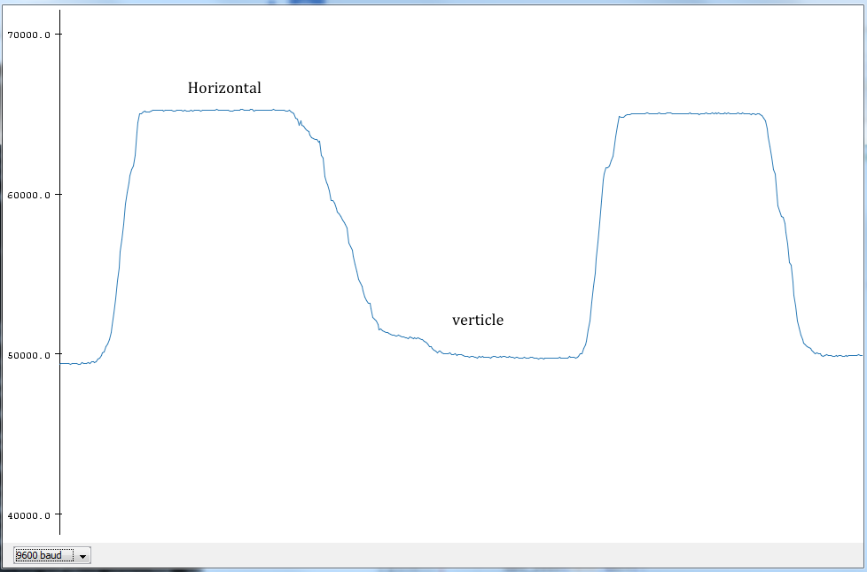
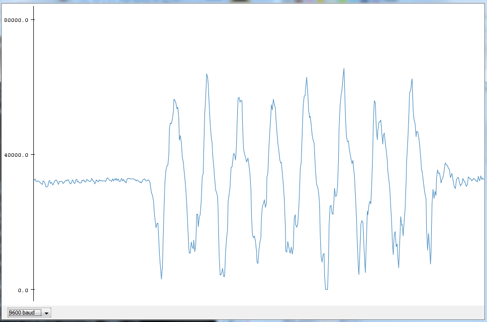
The code runs successfully and I used the arduino serial plot to visualize the data. One tricky thing about serial here is the Tx on the microcontroller should go the Rx on the FTDI cable, and vise versa.
Accelerometer test, AcY. The left one is changing the direction of the board to change the g force. The right one is shaking it.
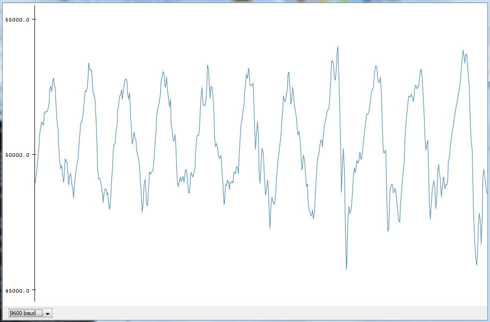
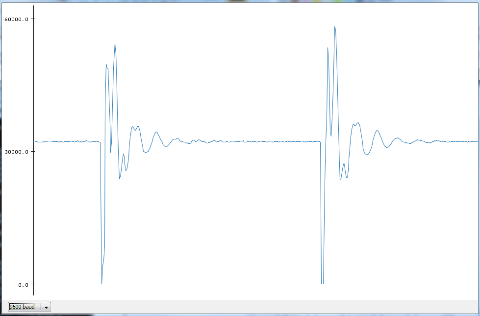
Gyroscope test, GyroY,the left one is rotating it forth and back, the right one is with a touch and let it stablize.
Besides input devices I also try to burn boot loader and use serial instead of SPI interface to upload program. I encounter many problems and spent really long time to figure it out. I used Optiboot which is a really compact bootloader about 512bytes. First need to generate the hex file for the bootloader, and I am using 20MHz oscillator which is not a standard compile. To compile the bootloader, open the Makefile inside the optiboot folder in arduino. And copy the atmega328 portion while change the frequency to 20000000 and Low Fuse to F7 which is correct setting for 20MHz fuse according to the manual. Then compile the file by make atmega328_20MHz AVR_FREQ=20000000. After obtaining the hex file. Open the boards.txt in arduino and add a new board type by adding the following lines. Then after reboot arduino, it should appear in the board list. And burn the boatloader using FabISP. After done, we can upload program with the boot loader and the FabISP are no long needed. Because I didn't know the existence of Fabduino, my own design of the board doesn't have the a capacitor between reset and the DTR pin of the FDTI adaptor which result in unable to activate the boot loader, after soldering on a 0.1nF. I works magically. After burning the bootloader, you can either use Arduino IDE or avrdude to upload program. For avrdude, use arduino for programmer and specify com port and baud rate: avrdude -p atmega328p -P COM6 -c arduino -b115200 -U flash:w:$(PROJECT).c.hex
	Xiaomeng.name=Xiaomeng

	Xiaomeng.upload.tool=avrdude
	Xiaomeng.upload.protocol=arduino

	Xiaomeng.bootloader.tool=avrdude
	Xiaomeng.bootloader.unlock_bits=0x3F
	Xiaomeng.bootloader.lock_bits=0x0F

	Xiaomeng.build.board=AVR_PRO
	Xiaomeng.build.core=arduino
	Xiaomeng.build.variant=eightanaloginputs

	Xiaomeng.menu.cpu.8MHzatmega328=ATmega328 (5V, Internal 8 MHz, Optiboot 76k8)
	Xiaomeng.menu.cpu.8MHzatmega328.upload.maximum_size=32256
	Xiaomeng.menu.cpu.8MHzatmega328.upload.maximum_data_size=2048
	Xiaomeng.menu.cpu.8MHzatmega328.upload.speed=76800
	Xiaomeng.menu.cpu.8MHzatmega328.bootloader.low_fuses=0xE2
	Xiaomeng.menu.cpu.8MHzatmega328.bootloader.high_fuses=0xDE
	Xiaomeng.menu.cpu.8MHzatmega328.bootloader.extended_fuses=0x05
	Xiaomeng.menu.cpu.8MHzatmega328.bootloader.file=optiboot/optiboot_atmega328_8MHz.hex
	Xiaomeng.menu.cpu.8MHzatmega328.build.mcu=atmega328p
	Xiaomeng.menu.cpu.8MHzatmega328.build.f_cpu=8000000L

	Xiaomeng.menu.cpu.20MHzatmega328=ATmega328 (5V, 20 MHz, Optiboot 115K2)
	Xiaomeng.menu.cpu.20MHzatmega328.upload.maximum_size=32256
	Xiaomeng.menu.cpu.20MHzatmega328.upload.maximum_data_size=2048
	Xiaomeng.menu.cpu.20MHzatmega328.upload.speed=115200
	Xiaomeng.menu.cpu.20MHzatmega328.bootloader.low_fuses=0xF7
	Xiaomeng.menu.cpu.20MHzatmega328.bootloader.high_fuses=0xDE
	Xiaomeng.menu.cpu.20MHzatmega328.bootloader.extended_fuses=0x05
	Xiaomeng.menu.cpu.20MHzatmega328.bootloader.file=optiboot/optiboot_atmega328_20MHz.hex
	Xiaomeng.menu.cpu.20MHzatmega328.build.mcu=atmega328p
	Xiaomeng.menu.cpu.20MHzatmega328.build.f_cpu=20000000L